Inverter Braking Resistor Calculation
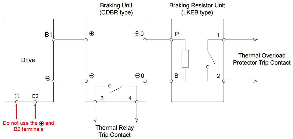
Connecting A Braking Resistor Or Cdbr Braking Unit To A Drive Smaller Models
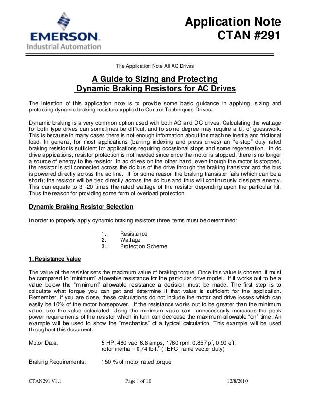
Dynamic Braking Resistor Selection Calculation

Inverter Drive Supermarket Brake Resistor Calculator
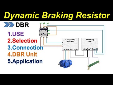
Dynamic Braking Resistor For Vfd Dbr Connection Rating Selection Hindi Youtube
Http Www Cpaltd Net Media Downloads Guide To Cpa Brake Resistors And Brake Choppers Pdf

Optional Devices Toshiba Inverter Tosvert Vf Series

Leave the watts entry blank or enter a value if you prefer to reduce the options.
Inverter braking resistor calculation.

Dynamic Braking Resistor Industrial Resistors

Resistors Physics Physics Projects Electronics Basics Diy Electronics Electronic Engineering
Pin Di House Wiring Diagram Inverter
Https Www Controlpanelproducts Co Uk Files Products 20 Braking 20resistor Cpp 20guide 20to 20braking 20resistor 20calculation Pdf
Source : pinterest.com
